Measurement Tools for Optical Coatings
Spectral Photometry
Standard spectrophotometric measurements in the wavelength range λ = 190 nm to 3200 nm are carried out with commercial spectrophotometers:
- PERKIN ELMER Lambda 1050®
- PERKIN ELMER Lambda 950®
- PERKIN ELMER Lambda 750®
- PERKIN ELMER Lambda 19®
- ANALYTIK JENA specord 250 plus®.
For measurements beyond this wavelength range, LAYERTEC is equipped with an FTIR spectrometer (λ = 1 to 20 μm) and a VUV spectrophotometer (λ = 120 to 300 nm). Please note that - over the full scale of the measurement range of R, T = 0 to 100 % - the absolute accuracy of the spectrophotometric measurement amounts to 0.2 to 0.4 %. For measurements with higher precision, a self-constructed set-up in the limited range T = 0.1 to 0.0001 % with an accuracy up to 0.2 ppm is available.

Cavity ring-down Spectroscopy
High reflectance and transmittance values in the order of R, T = 99.5 to 99.9999 % are determined by Cavity ring-down Time measurements. This method is an absolute measurement procedure with high accuracy, e.g. R = 99.995 % ±0.001 %. LAYERTEC operates various CRD systems which were developed in cooperation with research institutes and universities. A schematic representation of the CRD method is shown in Fig. 2.


Working Principle
A laser pulse is coupled into an optical cavity consisting of two highly reflecting mirrors. The intensity of the light is measured behind the cavity. At the beginning, the intensity increases during the pulse duration. Then it decreases exponentially with the time constant τ according to

with:

where c is the speed of light and L is the cavity length. RM is the geometric mean of the mirror reflectance and can be derived from the measurement of the time constant by

The accuracy of the measurement depends on the accuracy of the time measurement and the measurement of the cavity length. Please note that errors of beam adjustment will always lower the decay time and/or will cause multi-exponential Ring-Down curves. In case of a single- exponential decay (Fig. 3), stochastic errors cannot result in overstated reflectance values. Compared to a reflectance measurement in a spectrophotometer, CRD has two main advantages:
- It is applicable for very high reflectance and transmittance values when using an enhanced measurement set-up.
- It is impossible to get measurement values which exceed the real ones.
The reflectance of single mirrors can be derived from pairs of measurements of a triplet of mirrors with R1, R2 and R3 being the reflectance values of the mirrors 1, 2 and 3, respectively, and RM12, RM23 and RM13 being the measured geometric means of the reflectance for the pairs of mirrors with the corresponding numbers. Three measurements of mirror pairs provide:

Solving this system of equations the mirror reflectance can be calculated by:

In practice, this method is often used to determine the reflectance of a set of reference mirrors. Knowing the reflectance of a reference mirror, the reflectance of a specimen mirror can directly be derived using equation (3).

Broadband Cavity ring-down set-up and Applications
LAYERTEC has used CRD for the qualification of low loss mirrors for some years. Initially, there was the limitation that only discrete wavelengths, either generated by solid state lasers or diode lasers, could be used. The increasing demands concerning the optical properties of broadband mirrors required a measurement system for a spectral range over several hundreds of nanometers with a very high accuracy for measuring high reflectance values. So LAYERTEC developed a novel spectrally broadband Cavity ring-down time measurement system in cooperation with the Leibniz-Institute of Photonic Technology (IPHT) Jena e.V. [1]
[1] S. Schippel, P. Schmitz, P. Zimmermann, T. Bachmann, R. Eschner, C. Hülsen, B. Rudolph und H. Heyer: “Optische Beschichtungen mit geringsten Verlusten im UV-VIS-NIR-Bereich”, Tagungsband Thüringer Grenz- und Oberflächentage und Thüringer Kolloquium “Dünne Schichten in der Optik”, 7.– 9. September 2010, Gera; S. 268 – 282

An optical parametric oscillator (OPO), pumped by the third harmonic of a Nd:YAG laser, is used as light source. The use of harmonic conversion extends the tuning range towards the UV region and provides a measurement range from 210 to 1800 nm without gaps. In this measurement set-up, photo multipliers and avalanche diodes are used as detectors. The Ring-Down cavity can consist of two or three cavity mirrors. A two mirror cavity is used for reflectance measurements at 0° angle of incidence (Fig. 5 shows an example of such a measurement).
In contrast, a three mirror cavity set-up is used for measurements at obligue incidence angles with two mirrors mounted on precision rotary stages. This set-up can be used for wavelength scans at a constant angle or for angle resolved measurements at a constant wavelength (see Fig. 6). If the reflectance of two mirrors is known, the reflectance of the third mirror can be calculated. If the incidence of light is not perpendicular to the sample, the linear polarization of the OPO output beam can be rotated to set up perpendicular (s-) or parallel (p-) polarized light with respect to the sample over the entire spectral measurement range.


A standard cavity is used for the measurement of very high transmission values T > 99.5 % and of optical losses of components or gases in the cavity. For transmittance measurements the sample is placed between the cavity mirrors. As the sample is an additional optical loss for the cavity, the transmittance value can be calculated if the reflectance of the cavity mirrors is known. For measurements at a defined angle of incidence, the sample can be tilted in the range of 0° – 75° with respect to the optical axis of the cavity (Fig. 6b). Wavelength resolved measurements as well as angle resolved measurements are possible. The latter is very useful for the determination of the optimum angle for thin film polarizers (TFPs).


The same principle is used to determine optical losses of gases. First a spectrum of the evacuated cavity is measured. Then the cavity is filled with gas and the ring-down spectrum is measured again. The optical loss is calculated according to formula 6. As an example Fig. 9 shows the optical loss spectrum of ambient air.


Measurement reports can be provided on request. The broadband set-up permanently undergoes further development. The measurement capabilities and the performance increase steadily.
Laser-Induced Damage Threshold (LIDT)
LAYERTEC optics must be able to withstand extreme laser energies. In order to estimate the risk of possible damage to the coatings, the laser-induced damage threshold (LIDT) is determined.
Damage in optics for the continuous wave or short pulse regime (ns-range) is mainly related to thermal effects such as increased absorption – either due to the intrinsic absorption of the coating materials or absorption by defects – or poor thermal conductivity and low melting temperatures of the coatings. High power coatings require control of the intrinsic properties of the coating materials and the reduction of defects in the layers. Laser damage to picosecond and femto-second laser optics is mainly caused by field strength effects. Thus, high power coatings for these lasers require materials with large band gap and very special coating designs.
The determination of the laser-induced damage threshold (LIDT), according to the standards ISO 11254-1 (cw and 1-on-1, i.e. single pulse LIDT), ISO 11254-2 (S-on-1, i.e. multiple pulse LIDT) and ISO 11254-3 (LIDT for a certain number of pulses) requires laser systems operating under very stable conditions, precise beam diagnostics as well as online and offline damage detection systems. This is why a limited number of measurement systems with only a few types of lasers is available (e.g. for 1064 nm at Laser Zentrum Hannover). For some of the most prominent laser wavelengths, for example Argon ion lasers (488 nm or 514 nm), there is no measurement system available and certified LIDT data cannot be provided.
The 1-on-1 LIDT (i.e. 1 pulse on 1 site of the sample) is not representative for the normal operation conditions. However, these values can be used for comparing different coatings and for optimization procedures. The 1-on-1 values are directly related to the more practical S-on-1 LIDT (LIDT for a given number “S” of pulses on the same site of the sample). They can be interpreted as the upper limit of the LIDT. Laser systems with high repetition rates (some kHz) require lifetime tests expressed by LIDT values for high numbers of pulses.
LIDT Measurement Set-up at LAYERTEC

LAYERTEC has developed its own LIDT measurement set-up for in-house measurements with the aim to optimize the coatings concerning their stability against laser damage. The light source is a Q-switched Nd:YAG laser which can emit wavelengths of 1064, 532, 355 and 266 nm. The pulse duration is about 4 to 10 ns and the repetition rate is 10 Hz at all four possible wavelengths. A close-to-Gaussian shaped beam profile is generated by focusing the laser beam with a lens. The spot size is in the region of 200 to 1000 μm (1/e² radius). The actual value depends on the wavelength and the focal length of the lens. The set-up satisfies the requirements of ISO 11254. It has an online detection system based on a digital camera with fast image processing to inspect the sample for damage after every laser pulse. Online beam profile measurements and the determination of the energy density are done with a CCD camera beam profiler in combination with calibrated energy measuring heads with single pulse resolution. A motorized 3-axis stage and a sample holder for multiple pieces allow automated measurements at angles of incidence in the range of 0° to 60° either on reflecting or transmitting samples. The linear polarization of the laser beam can be oriented for either p- or s-polarization with the help of wave plates and a broadband polarizer for the desired wavelength. The measurement set-up is shown schematically in Fig. 10.

LAYERTEC tests samples by using its own procedure (please see next section), because the ISO standards deliver unreliable values for damage thresholds above 30 J/cm². However, if a measurement according to ISO 11254-2 is explicitly requested, the ISO procedure will be used. In this case, 100 or 1000 pulses will be used at each measurement position in order to minimize measurement time. This is not a test for longtime stability. However, LIDT results for 100 or 1000 pulses are more realistic in comparison to 1-on-1 LIDT results. Fig. 11 shows the result of a damage probability measurement according to ISO 11254-2.
The in-house LIDT measurements are mainly intended to compare LAYERTEC coatings among themselves for the purpose of coating and technology development. LAYERTEC provides LIDT results on request, but please note that these results are only valid for the specific measurement conditions (pulse duration, wavelength, number of pulses, beam shape, repetition rate).
LAYERTEC LIDT Testing Procedure for Pulsed Laser Sources
LAYERTEC has gained a lot of experience in laser damage testing by utilizing the LIDT testing procedures according to ISO 11254. However, it became clear that the measurements are both cost and time intensive but often deliver only questionable results. Significantly lower damage thresholds and strongly skewed damage probability distributions were observed in many cases. Troubleshooting the measurement set-up did not reveal any issues leaving only other reasons to explain the measurement errors.
As mentioned above, LAYERTEC uses a relatively large Gaussian-shaped laser spot to measure the damage threshold. The typical spot size is about 1 mm (1/e² diameter). Large spot sizes require a high laser energy and peak power to reach the fluence necessary to cause destruction at the testing site. Coatings with damage thresholds above 50 J/cm² require several hundreds of milli-joules laser pulse energy to show damage. In this case, large amounts of debris are generated and deposited within a circle of several millimeters in diameter around the damaged position. If an adjacent test site is located within this zone its damage threshold is significantly reduced due to the debris. This systematic error can be avoided by choosing a larger separation between the measurement positions while providing enough test sites. Very high damage thresholds above 100 J/cm² require a separation between adjacent positions of more than 10 mm.
The ISO standard assumes a symmetric distribution for the damage probability. LAYERTEC observes this behavior only at average damage thresholds below 30 J/cm². Threshold probability distributions with average damage values above 30 J/cm² are significantly skewed towards lower values. Assuming that the influence of debris can be neglected, the main reason for this phenomenon are imperfections in the coating and sometimes the surface quality itself. Contrary to ISO standards, significantly low threshold values should not be treated as statistical outliers. Strictly speaking, they have to be taken into account. Otherwise, damage threshold measurements would provide wrong values.
As discussed above, LIDT tests based on ISO standards are not viable for coatings with high damage thresholds. LAYERTEC developed an LIDT measurement method, which is well suited to measure the minimal damage threshold of optical coatings for high power or high energy laser applications. This procedure requires 4 to 7 testing positions with a separation of approximately 10 mm to each other on the sample. Wherever applicable, four identical samples with 25 mm in diameter are used to get 16 to 28 measuring positions per testing procedure. Every position is irradiated with stepwise increasing energy densities. The energy range of the test laser is subdivided into 50 levels. For the most part, 100 laser pulses are applied at each energy level to watch for cumulative effects in the coating. The starting energy has to be low enough to prevent any laser-induced damage. Then, the energy is increased until laser-induced damage occurs at the testing position.
All positions on the sample are irradiated in this way, until each position exhibits damage. For the purpose of measurement analysis, the highest, the average and the lowest measured damage threshold are reported. Further statistical analysis is not carried out. All stated damage threshold values measured by LAYERTEC were determined according to the LAYERTEC LIDT testing procedure for pulsed laser sources. Additional measurements were performed by several partners, e.g. Laser Zentrum Hannover, Laser Labor Göttingen and Friedrich Schiller University Jena.
Due to the limited number of measurement facilities and the need for lifetime tests in practical applications, it is also necessary to include the measurements and lifetime tests (cumulative irradiation tests) of several customers into a database. Please take into account that these values cannot be compared with a standardized LIDT measurement because the laser parameters given are those without damage. Besides, these values always come with a measurement error, especially with respect to the determination of the spot size. Errors in the order of about 30 % must be taken into account. Information about parameters for long-time operation will certainly convince the customer to use LAYERTEC optics. Sometimes, however, these tests will be required in the customer’s laser system. LAYERTEC supports such tests at the customer’s facility with a considerable discount for test samples.
Absorption Behavior
Photothermal Common-Path Interferometry (PCI)

A photothermal common-path interferometer (PCI) allows LAYERTEC to determine the absorption of optical thin films and bulk materials. In this set-up, an optical surface is irradiated by a pump laser, resulting in the absorption of part of the infalling radiation, see Fig. 14. Due to thermal conduction, the absorbed energy is dispersed as heat within the optics, leading to the formation of a thermal lens.
A second laser, the probe beam, irradiates the thermal lens which deforms the wavefront of said probe beam. This deformation leads to interference effects within the probe beam and can be measured as intensity variations with a photodetector. The magnitude of the wavefront deformation is proportional to the amount of energy absorbed by the optics. The pump beam is switched on and off periodically, with a modulation frequency of several 100 Hz. Thus, the intensity of the probe interference-pattern is temporally modulated as well.
Pump beams at 355 nm, 532 nm or 1030 nm are available for s- and p-polarized light, measurement may be conducted for angles of incidence between 10° and 70°. However, a transmittance above 1 % for the wavelength of the probe beam, 635 nm, is required. Apart from that, any HR, PR or AR coating (including single layers) on most common substrates may be measured. Substrates have to be plane with a thickness of 1 – 12 mm. Calibration reports are available on request.
Intra Cavity Heating Measurement (for coatings)

Absorption losses in optical coatings result in heating of coating and substrate. For average laser power levels above several kilowatts (cw), even low absorption losses in the range of some parts per million cause significant heating of the optical component. For example, the irradiated zone (1.5 mm in diameter) of an HR-coating with an absorption loss of 5 ppm at 1030 nm is heated to a temperature of about 80°C when exposed to a power of 80 kW.
LAYERTEC has built a heating measurement set-up for the purpose of quality assurance and technology development on high power optical components at a wavelength of 1030 nm. An Yb:YAG thin disc laser is used to generate a high power laser beam (Fig. 15). The set-up consists of a laser disc, a pump chamber, a sample (e.g. a highly reflective mirror) which works as a folding mirror, a second folding mirror, an output coupler, a laser power meter and a pyrometer for the temperature measurement. The beam spot size on the irradiated sample surface area is 1.5 mm (1/e²) in diameter. A very high intra cavity laser power of about 120 kW (cw) is achieved by choosing an output coupler with a relatively low transmittance value. Under these conditions, the power density on the sample is approximately 15 MW/cm².
Generally, coatings with a set-up-specific operating temperature lower than 100°C can be used for high power applications. Please note that the average temperature of the optical component measured is clearly lower than the temperature within the small irradiated zone on the coating.
For the purpose of achieving absolute absorption measurements, it is possible to calibrate the set-up with a set of samples with well-known absorption. The absorption measurement of the calibration samples was performed by using the LID (laser-induced deflection) measurement set-up at the Leibniz-Institute of Photonic Technology (IPHT) Jena e.V..
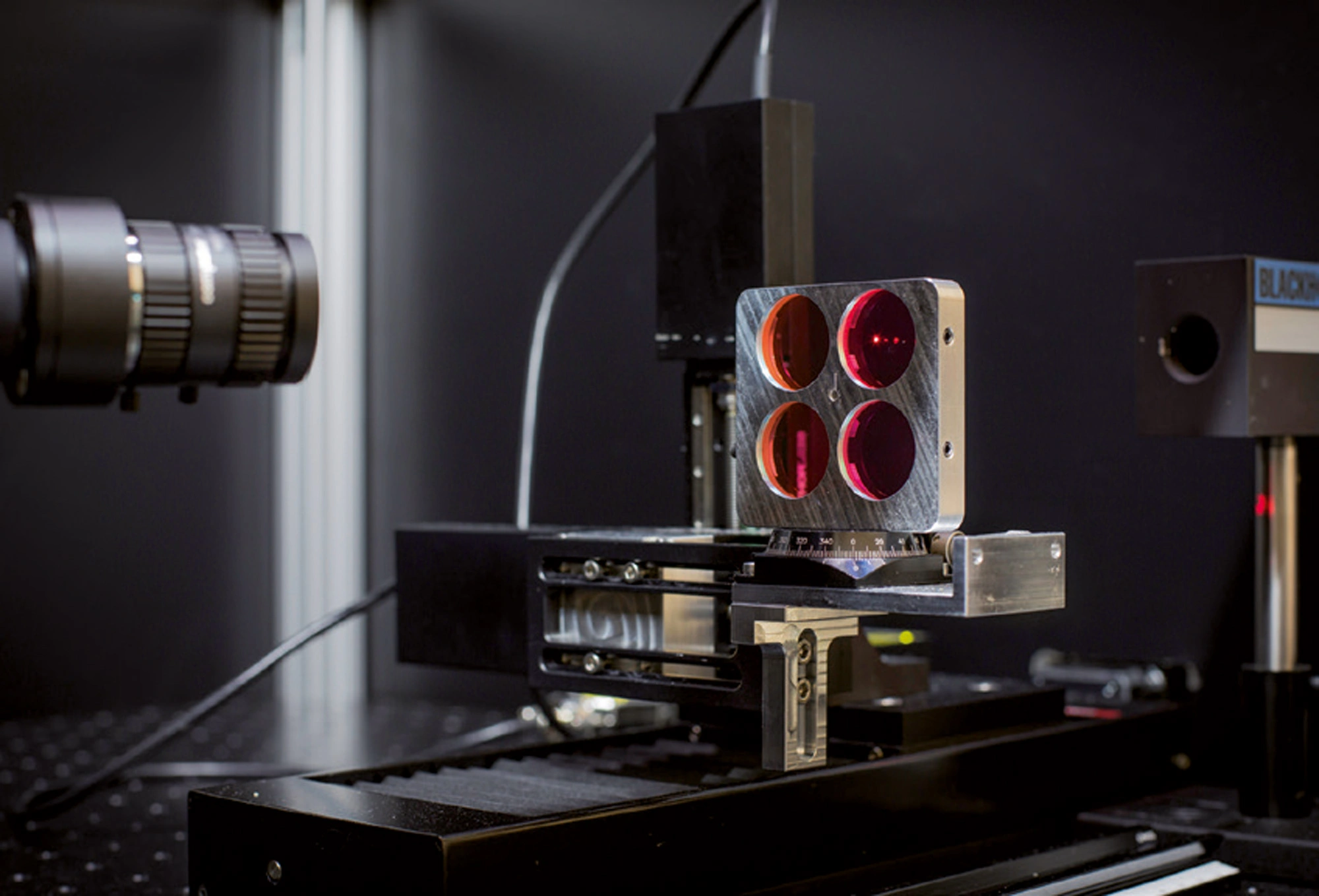
Defect Inspection System for Coatings
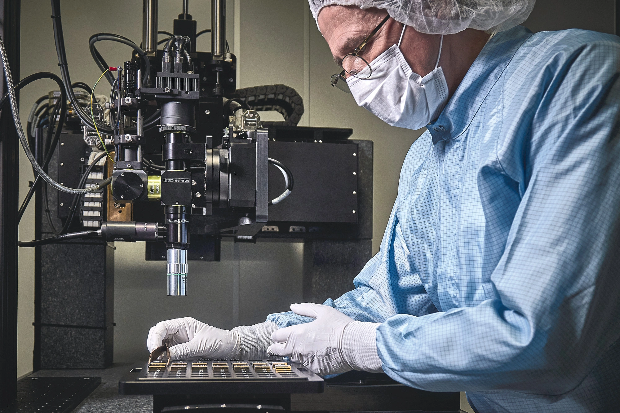
LAYERTEC built a measurement system capable of counting and classifying defects in optical coatings and on uncoated optical surfaces. The system detects down to 6 μm in size. It is able to inspect the complete surface of small as well as large optical components. Diameters Ø ≤ 600 mm and surface slopes up to 25° can be analyzed. Small to medium-sized pieces are placed in a special sample holder magazine which enables the automated measurement of a large number of pieces in a single inspection run (Fig. 16).
Measuring small defects is very challenging because the necessary microscope lenses have a very short depth of focus and require precise adjustment and positioning. Another important factor is proper lighting. Finally, the wide range of available geometries demands a very flexible control software, quickly adapting to new geometries in order to avoid collisions between the sample and the test system.
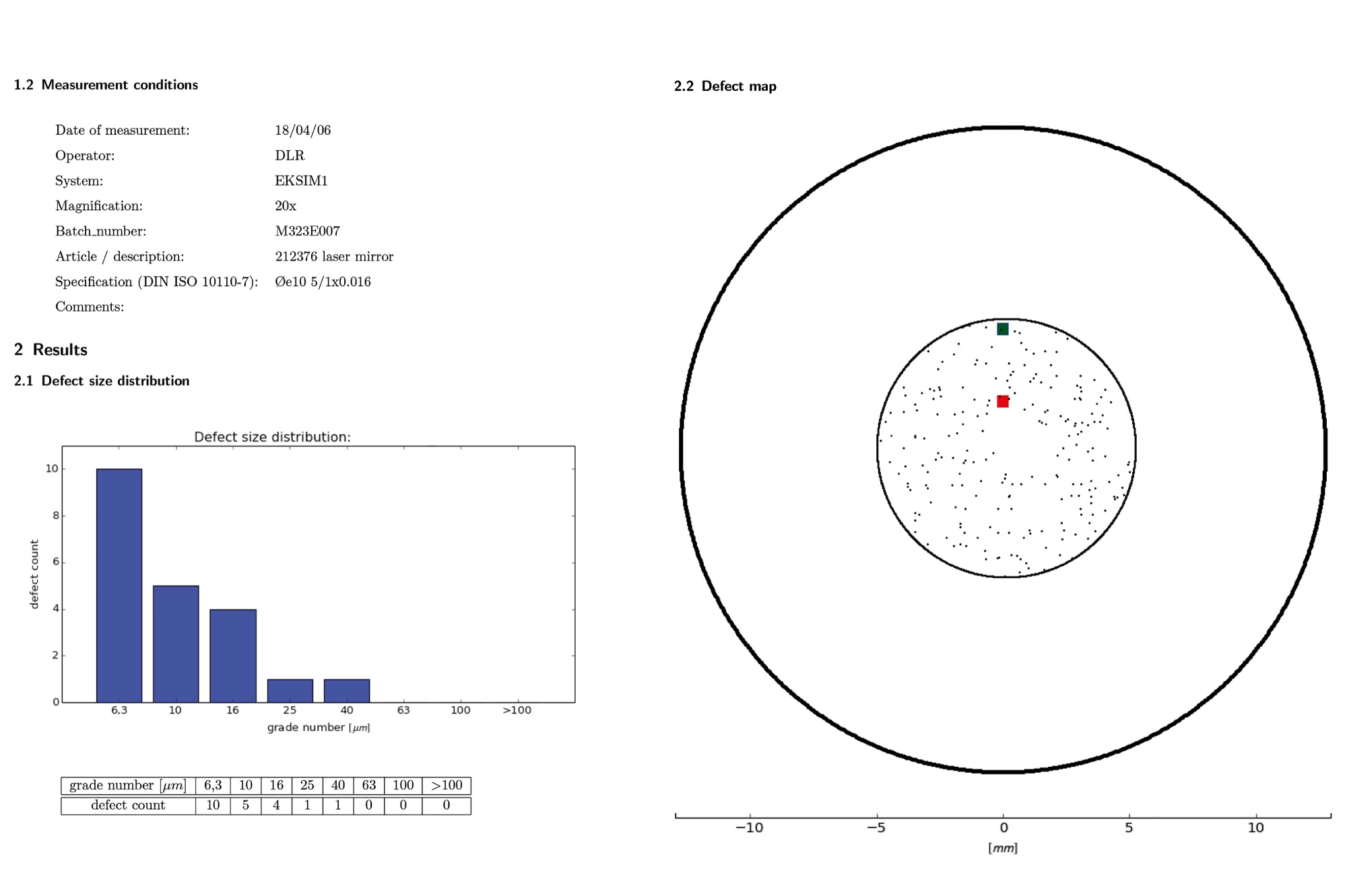
LAYERTEC constantly improves the system, enabling it to inspect cylindrical and aspherical optics while reducing effort and measurement time. Defects are classified by size according to ISO 10110-7 and their position on the optical surface is recorded. Thus, the complete set of microscopic imperfections on the optical surface can be visualized in a macroscopic defect map. Individual measurement reports, including defect maps and defect distributions, can be generated on request. An exemplary inspection report is shown in Fig. 17.
Address
LAYERTEC GmbH
Ernst-Abbe-Weg 1
99441 Mellingen
Germany
International Sales
US Sales Office
Social Media
© 2024 | LAYERTEC GmbH