Optical Interference Coatings
The purpose of optical coatings is to change the reflectance of optical surfaces. According to the materials used, metallic and dielectric coatings can be distinguished. Metallic coatings are used for reflectors and neutral density filters. The achievable reflectance is given by the properties of the metal. Common metals used for optical applications are described on page Metallic Coatings. Dielectric coatings use optical interference to change the reflectance of the coated surfaces. Another advantage is that the materials used in these coatings show very low absorption. The reflectance of optical surfaces can be varied from approximately zero (antireflection coatings) to nearly 100 % (low loss mirrors with R > 99.999 %) using optical interference coatings. These reflectance values are achieved only for a certain wavelength or a wavelength range.
The effect of optical coatings is based on three physical effects:
- Reflection of light at refractive index boundaries
- Interference of partial waves within the structure
- Exploitation of phase shift of the reflected waves at refractive index boundaries
Such structures are possible if transparent layers with plane-parallel interfaces can be deposited with a thickness of less than approx. 1 µm. Complex structures consist of alternating layers of several materials with specifically adjusted optical thickness.
Basics

The influence of a single dielectric layer on the reflectance of a surface is schematically shown in Fig. 1. An incident beam (a) is split into a transmitted beam (b) and a reflected beam (c) at the air-layer interface. The transmitted beam (b) is again split into a reflected beam (d) and a transmitted beam (e). The reflected beams (c) and (d) can interfere. In Fig. 1 the phase is represented by the shading of the reflected beams. The distance from “light-to-light” or “dark-to-dark” is the wavelength. Depending on the phase difference between the reflected beams, constructive or destructive interference may occur. The reflectance of the interface between the two media depends on the refractive indices of the media, the angle of incidence and the polarization of the light.
In general, it is described by the Fresnel equations:

For normal incidence (α = ß = 0°) the equations can be reduced to the simple expression:

The phase difference between the beams (c) and (d) (see Fig. 1) is given by the optical thickness n × t of the layer (the product of the refractive index n and the geometrical thickness t). Furthermore, a phase shift of π, i.e. one half-wave, has to be taken into account, if light coming from a low index medium is reflected at the interface to a high index medium. Please refer to the literature cited on page Literature for a detailed explanation of the physics of optical interference coatings. Below are a few rules to help customers understand the optical properties of the coatings described in this catalog:
- High index layers increase the reflectance of the surface. The maximum reflectance for a given wavelength λ is reached for n × t = λ/4. Only in the case of an optical thickness n × t = λ/2, the reflectance of the surface does not change for this wavelength λ.
- Low index layers decrease the reflectance of the surface. The minimum reflectance for a given wavelength λ is reached for n × t = λ/4. Only in the case of an optical thickness n × t = λ/2, the reflectance of the surface does not change for this wavelength λ.
Antireflective Coatings (AR)
A single low index layer can be used as a simple AR coating. The most common material for this purpose is magnesium fluoride with a refractive index of n = 1.38 in the VIS and NIR. This material reduces the reflectance per surface to R ≈ 1.8 % for Fused Silica and nearly zero for sapphire.
Single wavelength AR coatings consisting of 2 to 3 layers can be designed for all substrate materials to reduce the reflectance for the given wavelength to nearly zero. These coatings are used especially in laser applications. AR coatings for several wavelengths or for broad wavelength ranges are also possible and consist of 4 to 10 layers.


Mirrors and Partial Reflectors
The most common mirror design is the so-called quarter-wave stack, i.e. a stack of alternating high and low index layers with equal optical thickness of n×t = λ/4 for the desired wavelength. This arrangement results in constructive interference of the reflected beams arising at each interface between the layers. The spectral width of the reflection band and the maximum reflectance for a given number of layer pairs depend on the ratio of the refractive indices of the layer materials. A large refractive index ratio results in a broad reflection band while a narrow reflection band can be produced using materials with a low refractive index ratio.


To visualize the effect of different refractive index ratios, Fig. 4 compares the reflectance spectra of quarter-wave stacks consisting of 15 pairs of Ta2O5 + SiO2 (Δn ≈ 0.66) and TiO2/SiO2 (Δn ≈ 0.91) for 800 nm.
The theoretical reflectance will approach R = 100 % with an increasing number of layer pairs, assuming that ideal coatings have zero absorption and scattering losses. Partial reflectors with several discrete reflectance values between R = 0 % and R = 100 % can be manufactured using only a small number of layer pairs (see Fig. 5). Adding non-quarter-wave layers to a stack optimizes the reflectance to any desired value.

Fig. 5 also shows that an increasing number of layer pairs results in steeper edges of the reflectance band. This is especially important for edge filters, i.e. mirrors with low reflectance side bands. Extremely steep edges require a large number of layer pairs which also results in a very high reflectance (HR). Extremely high reflectance values require very low optical losses. This can be achieved by using sputtering techniques.
Dielectric Broadband Coatings
The first step to broadband mirrors and output couplers is to use coating materials with a large refractive index ratio. The bandwidth can be further increased by using special coating designs i.e. by using non-quarter-wave layers.
The easiest way is to combine two or more quarter-wave stacks with overlapping reflectance bands. However, this results in an increase of optical losses at the wavelengths where the bands overlap. Moreover, multiple stack designs cannot be used for ultrafast lasers because they induce pulse distortion.
LAYERTEC offers special all-dielectric broadband components for ultrafast lasers up to a bandwidth of one octave, i.e. 550 nm – 1100 nm (see page Octave Spanning Ultrafast Laser Optics (400 – 500 nm Bandwidth))
An even larger bandwidth can be achieved using metals. However, the natural reflectance of metals is limited to 92 – 99 % (see page Metallic Coatings), but it can be increased by dielectric coatings. For such ultra-broadband metal-dielectric mirrors see page Broadband and Scanning Mirrors (300 – 2500 nm) and Front Surface Silver Mirrors (400 – 4000 nm).
Optical Losses
Light, which impinges on an optical component is either reflected, transmitted, absorbed or scattered. From this basic point of view, the energy balance can be written in the simple equation
R + T + A + S = 1 (with R … Reflectance, T … Transmittance, A … Absorption and S … Scattering).
In laser physics and precision optics absorption and scattering are summarized as optical losses because the absorbed and scattered part of the incoming light can no longer be used as a carrier of information or as an optical tool. In practice, the reflectance which can be achieved depends on the absorption and scattering losses of the optics.
Scattering losses increase drastically with decreasing wavelength, which can be described by the Mie theory (scattering by particles with diameters in the order of λ, S ~ 1/λ²) and Rayleigh theory (scattering by particles with diameters < λ, S ~ 1/λ4). Depending on the surface and bulk structure, Mie and Rayleigh scattering occur simultaneously. Scattering losses depend critically on the microstructure of the coatings and as such on the coating technology used. Usually, coatings produced by evaporation techniques show significantly higher scattering losses than coatings produced by magnetron sputtering or ion beam sputtering. The strong dependence of the scattering losses on the wavelength is the reason why scattering losses are a huge problem in the UV range while they are less important in the NIR and beyond.
Absorption in optical coatings and substrates is mainly determined by the band structure of the materials. Common oxide materials show band gaps of 3 to 7 eV which correspond to absorption edges in the NUV and DUV. Fluorides have band gaps of 9 to 10 eV resulting in absorption edges in the VUV spectral range (for more information please see page Fused Silica). Some materials also show absorption bands in addition to the basic absorption edge as seen in the absorption band of Si-O-H bonds in Fused Silica around 2.7 µm. Defects in the layers form absorbing states in the band gap of the materials. These defects may result from contaminations or from the formation of non-stoichiometric compounds. Optical coatings must be optimized with respect to low contamination levels and good stoichiometry. This kind of absorption losses also increases with decreasing wavelength.
The amount of all kinds of losses depends on the thickness of the layer system. Each layer pair increases the theoretical reflectance; however, in practice, it also increases the optical losses. There is an optimum number of layer pairs which generates the maximum reflectance, especially for evaporated coatings with relatively large scattering losses.
| Wavelength Range | Materials | Coating Technology | Reflectance |
|---|---|---|---|
| ≈ 200 nm | fluorides | evaporation | > 98.0 % |
| ≈ 250 nm | oxides | IAD sputtering | > 99.0 % > 99.7 % |
| ≈ 300 nm | oxides | IAD sputtering | > 99.5 % > 99.9 % |
| ≈ 350 nm | oxides | IAD sputtering | > 99.8 % > 99.95 % |
| VIS | oxides | IAD sputtering | > 99.9 % > 99.95 % |
| Low Loss Mirrors VIS | oxides | sputtering | > 99.99 % |
| NIR | oxides | IAD sputtering | > 99.9 % > 99.98 % |
| Low Loss Mirrors NIR | oxides | sputtering | > 99.998 % |
Stress
Another effect which limits the number of layers is the mechanical stress in the coating. This stress results from the structure of the layers but also from different thermal expansion coefficients of substrate and coating. Mechanical stress may deform the substrate, but it may also result in cracks in the coating or in a reduced adherence of the coating.
Stress can be limited by material selection and the optimization of process temperature, deposition rate and, in case of ion assisted and sputtering processes, ion energy and ion flux.
Angle Shift
A special feature of interference coatings is the angle shift. It means that features shift to shorter wavelengths with increasing angle of incidence. Turning an optical component from AOI = 0° to AOI = 45° results in a downshift of the features by about 10 %. The angle of incidence must be known to design any optical coating. Moreover, polarization effects must be taken into account at non-normal incidence (see below).
Please note that the angle of incidence varies naturally if curved surfaces are used. Lenses in an optical system always have a range of acceptance angles which is determined by the shape of the lens and by the convergence or divergence of the beam. If these features are known, AR coatings can be improved significantly. Besides the shift, broadband AR coatings often show an increased reflectance at AOI ≥ 30° (see Fig. 6a).
The angle shift offers the possibility of angle adjustment of an interference coating. This is especially useful in the case of filters and thin film polarizers. These optics show extremely narrow spectral ranges of optimum performance. It may decrease the output and increase the costs drastically if the specifications for wavelength and AOI are fixed. Angle adjustment (see Fig. 6b) is the best way to optimize performance and to minimize costs.


Polarization Effects
Besides angle shift, polarization effects appear at non-normal incidence. For optical interference coatings, it is sufficient to calculate the reflection coefficients for s- and p-polarized light. The reflectance of unpolarized light is calculated as the average of Rs and Rp.

To explain the meaning of the terms s-polarization and p-polarization, a reference plane must be determined (see lower part of Fig. 7). This plane is defined by the incident beam and by the surface normal of the optic. “S-polarized light” is that part of the light which oscillates perpendicularly to this reference plane (“s” comes from the German word “senkrecht” = perpendicular). “P-polarized light” is the part which oscillates parallel to the reference plane. Light waves with a plane of oscillation inclined to these directions, are split into p-polarized and s-polarized parts.
The upper part of Fig. 7 shows the reflectance of a glass surface vs. AOI for s- and p-polarized light. The reflectance for s-polarized light increases with increasing angle of incidence. The reflectance for p-polarized light decreases initially, with R reaching 0 % at Brewster’s angle and then increasing again as the angle of incidence extends beyond Brewster’s angle. In principle, the same applies for dielectric mirrors. For AOI ≠ 0°, the reflectance for s-polarized light is higher and the reflection band is broader than for p-polarized light.

In case of edge filters, where one of the edges of the reflectance band is used to separate wavelength regions of high reflectance and high transmittance, non-normal incidence results in a separation of the edges for s- and p-polarized light as the polarizations experience different angle shifts. Thus, for unpolarized light the edge is broadened considerably.
Documentation of Coating Performance at LAYERTEC
LAYERTEC includes a data sheet of transmittance and/or reflectance for each delivered optical component. The standard procedure is to measure the transmittance of the optics at AOI = 0°. A mathematical refinement of the theoretical design to this measured spectrum is carried out and the reflectance at the desired AOI is calculated from this fit. Sputtered optical coatings for the VIS and NIR exhibit extremely low scattering and absorption losses (both in the order of some 10-5). This has been confirmed in direct measurements of scattering and absorption as well as via highly accurate reflectance measurements (e.g. by Cavity ring-down spectroscopy). The reflectance of sputtered mirrors can be approximated by measuring the transmittance T and using the simple formula
R = 100 % – T
due to very small the optical losses. In a normal spectrophotometer, the transmittance can be measured with an accuracy of about 0.1 to 0.2 % (depending on the absolute value); whereas reflectance measurements in spectrophotometers mostly have errors of about 0.5 %. Thus, determining the reflectance of sputtered coatings in the VIS and NIR via transmittance measurements is much more accurate than direct reflectance measurements. Please note that this method can only be applied because the optical losses are very small (which is one of the advantages of sputtered coatings). The method is also used for evaporated coatings in the UV to NIR spectral range where the optical losses are only about 10-3 and can be included into the reflectance calculation. In the DUV range, the coatings usually show scattering losses in the order of 10-3 … 10-2, depending on the wavelength. That is why, for example, fluoride coatings for wavelengths below 220 nm are delivered with direct reflectance measurements. Direct reflectance measurements are also necessary for low-loss mirrors. LAYERTEC has a Cavity ring-down set-up for spectrally resolved measurements in the wavelength range between 210 to 1800 nm.
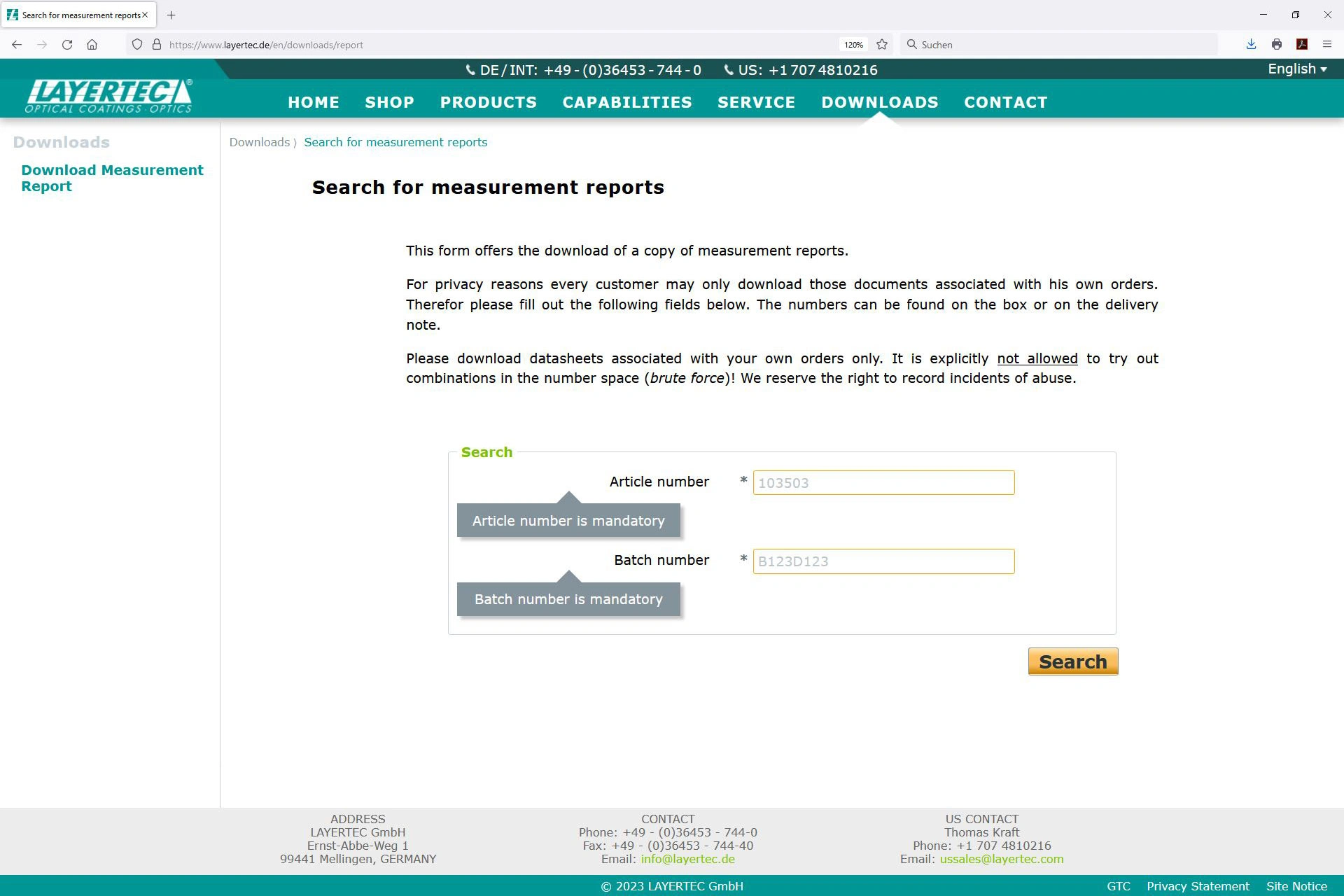
The data sheets are available and can be downloaded from the LAYERTEC website. Fig. 9 shows the download window for data sheets. To avoid mistakes, registration is required for batch number and part number.
Address
LAYERTEC GmbH
Ernst-Abbe-Weg 1
99441 Mellingen
Germany
International Sales
US Sales Office
Social Media
© 2024 | LAYERTEC GmbH